Thermoelectric Generator: Difference between revisions
Initial commit |
→Blowers: Out of date info |
||
| (37 intermediate revisions by 8 users not shown) | |||
| Line 1: | Line 1: | ||
''See Also: [[Power_Grid|Power Grid]]'' | |||
| | |||
}} | The thermoelectric generator (TEG) is the main source of power on [[Cogmap1]], [[Cogmap2]], [[Atlas]], and [[Kondaru]]. It generates power via the thermal interaction of hot gas and cold gas inside the generator. In order to create and maintain a supply of hot and cold gas, two separate loops of gas pipes move through the TEG: The hot loop and the cold loop. As their names imply, the hot loop has equipment designed to heat up the gas within, and the cold loop has equipment designed to cool down the gas within. | ||
==Parts of the TEG== | |||
===Core=== | |||
<tabs> | |||
<tab name="Cogmap1"> | |||
[[File:Cogmap1_TEG_Core.png|350px|thumb]] | |||
</tab> | |||
<tab name="Cogmap2"> | |||
[[File:Cogmap2_TEG_Core.png|350px|thumb]] | |||
</tab> | |||
<tab name="Kondaru"> | |||
[[File:Kondaru_TEG_Core.png|350px|thumb]] | |||
</tab> | |||
<tab name="Atlas (Off-Rotation)"> | |||
[[File:Atlas_TEG_Core.png|350px|thumb]] | |||
</tab> | |||
</tabs> | |||
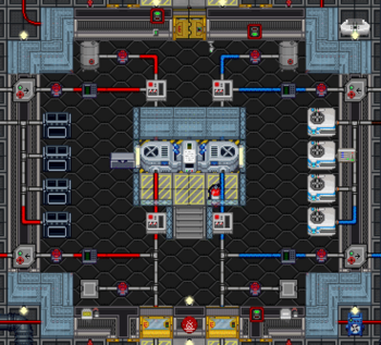
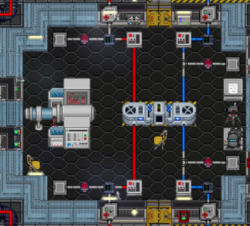
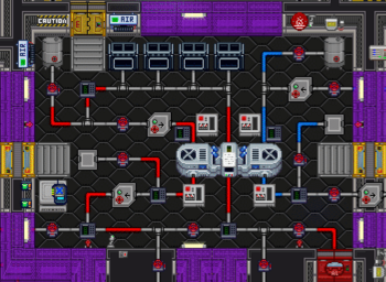
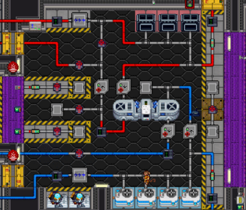
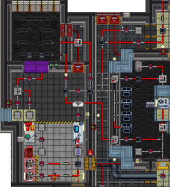
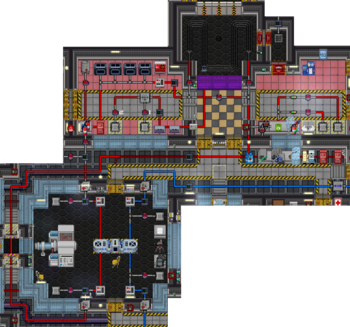
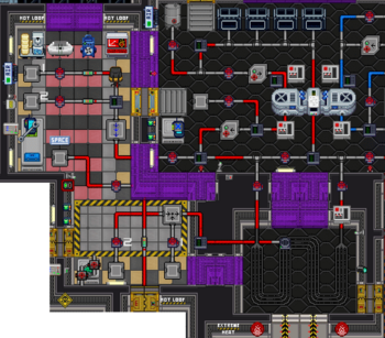
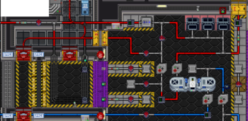
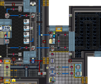
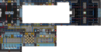
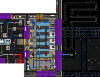
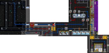
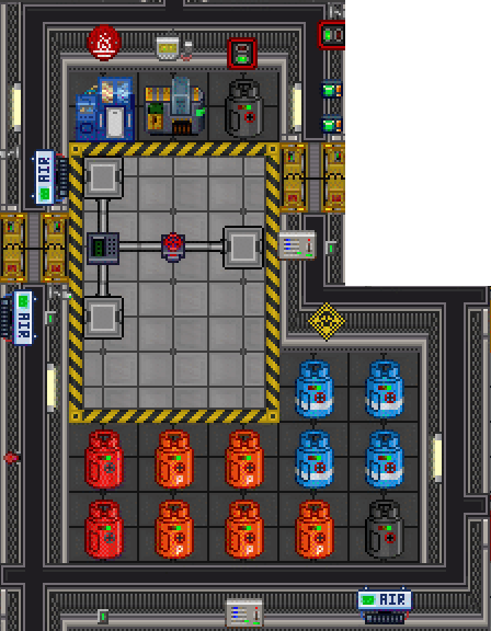
The TEG core itself is what makes the electricity. It functions by taking a part of the heat energy conducted between the hot loop and cold loop and converting it into electrical power. The central part of the TEG contains a status terminal, which can give you stats on the current power output, the pressure of the inlet and outlet of both gas loops, and the temperature of both gas loops. The graphic displayed on this terminal represents the current power generation of the TEG. '''Even the graphics that seem to indicate danger, like skulls and explosions, are only indicative of power output and are not a cause for concern.''' | |||
The TEG core also features some warning lights next to the blowers. These lights will be blue when blower status is nominal. If the blowers are consuming more power than the APC is receiving, the lights will turn yellow when power is expected to fail within the next five minutes, and will turn red when power is expected to fail in one minute. Due to the questionable math involved in power calculations, the lights turning yellow should not be cause for any concern unless it does not turn blue again after a minute or so. | |||
====Blowers==== | |||
The turbines on the left and right sides of the TEG are gas blowers designed to help increase the flow of gas through the TEG. Using an empty hand, their target minimum pressure can be set, and they can be turned on and off. While on, the blower will attempt to pull gas through the pipe in order to maintain at least as much outlet pressure as the specified value. They consume power from the local APC while active, with the power draw being determined by the the difference between the outlet pressure and the inlet pressure. Larger pressure differentials require more power to push gas against. | |||
=====Lubricant===== | |||
The maintenance panel on the blowers can be accessed by using a screwdriver on them. Each blower contains a lubricant tank, which starts filled with 200 units of [[oil]]. The lubricant tanks can be emptied by using a wrench on them to open the drain caps, which will leak the existing lubricant onto the floor. Remember to close the drain caps before adding new lubricant in order to not waste it. | |||
The quality of the lubricant effects how effectively and power-efficiently the blowers are able to operate against a pressure differential, with more slippery chemicals such as [[Chemicals#Space_Lube|space lube]] and [[Chemicals#Organic_Superlubricant|organic superlubricant]] providing greater efficiency. The total blower boost from the lubricant is based on the quantity and quality of the lube, meaning that filling the blowers to capacity will be more effective. | |||
Other chemicals may do even more things aside from just lubricating the blowers. For example, [[pyrosium]] or [[cryostylane]] reacting with oxygen in the blowers will change the temperature of the gas that passes through the blower. | |||
====Semiconductor==== | |||
Inside the central piece of the TEG is a prototype semiconductor, which can be removed by using a screwdriver, then wirecutters, then a crowbar on the TEG. After being removed, the semiconductor can be plated in another material using the [[Ore_Processing#Arc_Electroplater|arc electroplater]], which will change how efficiently the TEG extracts electrical power from the heat exchange. For optimal engine performance, a semiconductor that is electrically conductive and thermally insulative is ideal. To re-add the semiconductor to the engine, use the semiconductor, then wires, then wire cutters, then a screwdriver. | |||
===Hot Loop=== | |||
<tabs> | |||
<tab name="Cogmap1"> | |||
[[File:Cogmap1_TEG_Hot.png|350px|thumb]] | |||
</tab> | |||
<tab name="Cogmap2"> | |||
[[File:Cogmap2_TEG_Hot.png|350px|thumb]] | |||
</tab> | |||
<tab name="Kondaru"> | |||
[[File:Kondaru_TEG_Hot.png|350px|thumb]] | |||
</tab> | |||
<tab name="Atlas (Off-Rotation)"> | |||
[[File:Atlas_TEG_Hot.png|350px|thumb]] | |||
</tab> | |||
</tabs> | |||
The hot loop is all of the pipeworks and equipment dedicated to heating gas and pushing it through the TEG. It features two gas tank ports designed to inject plasma into the hot loop pipes for the purpose of conducting thermal energy. In order to raise the temperature of the gas, the hot loop comes equipped with furnaces and a burn chamber. The hot loop pipes are a distinct red color, as are the floor tiles in most hot loop rooms. | |||
====Furnaces==== | |||
The furnaces can accept any flammable solid as fuel. The most readily available is [[Guide_to_Mining#Char|char]], but [[Guide_to_Mining#Plasmastone|plasmastone]], [[Guide_to_Botany#Cannabis|weed]], paper, and even corpses can be used as fuel. Different types of fuel do not burn hotter, though more flammable things will fill up the furnace more than less flammable things. The furnace heats to roughly 3200 kelvin when full, and starts to notably drop off in temperature when less than 2/3 full. | |||
Do note that the furnaces attempt to force the gas in the loops towards their output temperature, regardless of whether this means heating the gas or cooling it. '''If you have a decently hot chamber burn running, running the furnaces will actually cool your hot loop down.''' | |||
====Burn Chamber==== | |||
The burn chamber is the other method of generating heat in the hot loop. Using the combustion of plasma and oxygen over a hot loop radiator, it can create significantly higher temperatures than the furnaces are capable of. Like the hot loop pipes, the burn chamber has two gas tank ports designed to add gas to the chamber. Unlike the pipes however; these connector ports feed into a special gas mixer pump before reaching the burn chamber. Using the associated mixer pump control terminal, you can set the ratio of the contents of the two gas tanks and the pressure at which they are released into the burn chamber. While experimental burns may benefit from more precise mixer settings, leaving the pump set to a 1:1 ratio of oxygen and plasma at atmospheric pressure (101.325kPa) will ensure a long-lasting and hot burn. | |||
Do note that the burn chamber is not perfectly insulated. A particularly hot burn will heat up the chamber walls, causing heat to conduct out of the chamber and into the surrounding areas. While the heat shields button to deploy shields over the observation windows may help somewhat, it is common practice to use an RCD to cut holes in the floor of the surrounding rooms, venting the engine room and preventing it from spreading dangerously hot gas to the rest of the station. | |||
===Cold Loop=== | |||
<tabs> | |||
<tab name="Cogmap1"> | |||
[[File:Cogmap1_TEG_Cold.png|350px|thumb]] | |||
</tab> | |||
<tab name="Cogmap2"> | |||
[[File:Cogmap2_TEG_Cold.png|350px|thumb]] | |||
</tab> | |||
<tab name="Kondaru"> | |||
[[File:Kondaru_TEG_Cold.png|350px|thumb]] | |||
</tab> | |||
<tab name="Atlas (Off-Rotation)"> | |||
[[File:Atlas_TEG_Cold.png|350px|thumb]] | |||
</tab> | |||
</tabs> | |||
The cold loop is all of the pipeworks and equipment dedicated to cooling gas and pushing it through the TEG. It features two gas tank ports designed to inject plasma into the hot loop pipes for the purpose of dissipating thermal energy. In order to lower the temperature of the gas, the cold loop comes equipped with a space radiator and coolers. The cold loop pipes are a distinct blue color, as are the floor tiles in most cold loop rooms. | |||
====Space Radiator==== | |||
A section of the cold loop exits the station in order to flow through radiator pipes in outer space. Due to the extreme cold of space (2.7 degrees above absolute zero, to be exact), this radiator is able to cool the gas in order to dispose of the energy transferred into it by the hot loop. There is nothing user-configurable about the radiator, other than making sure to open the valves so the gas can actually reach it. | |||
====Coolers==== | |||
Something of a counterpart to the hot loop's furnaces, the coolers expend electricity in order to lower the temperature of the cold loop. They can cool the cold loop down to a minimum of 70.3 degrees kelvin, or -200 degrees celsius. Like the furnaces the coolers will attempt to force the gas in the loops towards their output temperature, regardless of whether this means cooling the gas or heating it. '''Unless the cold loop is absorbing enough energy to keep it above -200 degrees celsius, turning on the coolers will actually warm the cold loop up.''' | |||
===Gas Storage=== | |||
<tabs> | |||
<tab name="Cogmap1"> | |||
[[File:Cogmap1_TEG_Gas.png|300px|thumb]] | |||
</tab> | |||
<tab name="Cogmap2"> | |||
[[File:Cogmap2_TEG_Gas.png|300px|thumb]] | |||
</tab> | |||
<tab name="Kondaru"> | |||
[[File:Kondaru_TEG_Gas.png|300px|thumb]] | |||
</tab> | |||
<tab name="Atlas (Off-Rotation)"> | |||
[[File:Atlas_TEG_Gas.png|300px|thumb]] | |||
</tab> | |||
</tabs> | |||
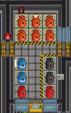
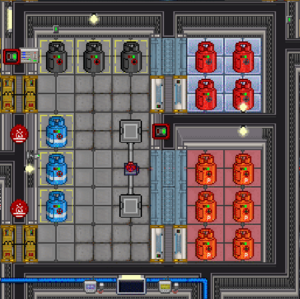
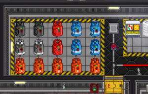
Gas storage is where all of the canisters of gas that you may or may not need in order to run the engine are stored. It also contains some other helpful equipment, such as air scrubbers and the [[Making_and_Breaking#Gas_Extractor|gas extractor]]. | |||
====Plasma==== | |||
[[File:PlasmaCanister.png|64px]] | |||
The blood of a functioning engine. Plasma has an absurd heat capacity compared to other gasses, making it extremely efficient for moving thermal energy through the pipes. It is also quite flammable in the presence of gaseous oxygen, which makes it vital in the burn chamber too. However, plasma's volatility means that if hot plasma were to escape from a ruptured pipe, it would combust rapidly in the air and lead to a massive fire in the engine room. | |||
====Oxygen==== | |||
[[File:OxygenCanister.png|64px]] | |||
The stuff you breathe, and also vital for combustion to happen. If you are running the burn chamber, you will need some of this alongside plasma in order to get an actual fire. | |||
====Nitrogen==== | |||
[[File:N2Canister.png|64px]] | |||
The other stuff you breathe, and also vital for literally nothing. Perhaps an NT executive mistook some of these useless red canisters for the extremely useful orange canisters of plasma, causing them to be included in the engine gas storage room by accident. This gas has no use at all, and has a terrible heat capacity. | |||
====Carbon Dioxide==== | |||
[[File:CO2Canister.png|64px]] | |||
This invisible, asphyxiating gas has no usage in combustion and has a subpar heat capacity, though certain "[[Antagonist|motivated]]" crew members may find some use for it as an area-denial weapon with a bit more subtlety than a full-on plasma flood. It is more commonly seen as a byproduct of combustion in the burn chamber, where managing carbon dioxide through usage of the chamber exhaust vents or other means is important to ensure that it does not smother the burn and extinguish it. | |||
==Basic Startup Procedure== | |||
The purpose of the following two startup guides are to offer a simple explanation of how the engine may be set up to generate power. These setups are by no means even close to optimal, and instead favor stability and ease-of-setup. | |||
===Furnace Burn=== | |||
These steps will guide you through how to make a basic char burn in the furnaces. If the round lasts longer than 45 minutes or so, the furnaces may need refueling to maintain output levels. | |||
# '''Light the furnaces''': Locate the fuel crates full of char somewhere in the engine, and bring the char to the furnaces. Fill each furnace full of char and turn them on. | |||
# '''Connect the plasma tanks''': Locate plasma tanks from gas storage. Connect two tanks to the hot loop connector ports and two tanks to the cold loop connector ports by using a wrench on them. | |||
# '''Turn the valves''': Turn valves so that the flowing gas has an available path from the connector ports in order to flow through the TEG. Make sure to turn any valve needed for the gas to reach the furnaces and space radiator too, as some TEGs have bypass valves that allow you to prevent gas from reaching these equipment. Avoid turning the gas purge valves, as these lead to a vent in space and are meant for emptying the pipes of gas. | |||
# '''Configure the blowers''': Use a multitool on a blower on the side of the TEG to access its configuration menu. Set its target pressure to 1000kPa, and activate it. Repeat for the other blower. | |||
# '''Configure the SMES units''': The engine should be producing power by this point, and so the [[Power_Grid#SMES|SMES units]] will need to be configured to distribute the power. On some maps some of them may be a considerable distance from the engine, and so asking a knowledgeable [[AI]] to set them for you may be helpful. | |||
===Chamber Burn=== | |||
These steps will guide you through how to make a basic plasma burn in the burn chamber. | |||
# '''Connect the plasma tanks''': Locate plasma tanks from gas storage. Connect '''one''' tank to the hot loop connector port and two tanks to the cold loop connector ports by using a wrench on them. Connecting two tanks may cause the pipes to burst from overpressure. | |||
# '''Turn the valves''': Turn valves so that the flowing gas has an available path from the connector ports in order to flow through the TEG. Make sure to turn any valve needed for the gas to reach the burn chamber and space radiator too, as some TEGs have bypass valves that allow you to prevent gas from reaching these equipment. Avoid turning the gas purge valves, as these lead to a vent in space and are meant for emptying the pipes of gas. | |||
# '''Light the chamber''': Connect a plasma tank and an oxygen tank to the burn chamber connector ports, and open the chamber fuel valves. Find the mixer pump control terminal (a computer with a whiteish screen, usually near the other computers) and turn on the mixer pump. Leave the gas ratio and pressure to their default values (50%:50%, 101.325kPa). After allowing the gas to enter the chamber for a few seconds, locate the ignition switch to create a spark to ignite the gas. If the fire stays in place and does not spread, throw the ignition switch again. | |||
# '''Configure the blowers''': Use a multitool on a blower on the side of the TEG to access its configuration menu. Set its target pressure to 1000kPa, and activate it. Repeat for the other blower. | |||
# '''Configure the SMES units''': The engine should be producing power by this point, and so the [[Power_Grid#SMES|SMES units]] will need to be configured to distribute the power. On some maps some of them may be a considerable distance from the engine, and so asking a knowledgeable [[AI]] to set them for you may be helpful. | |||
==Additional Mechanics== | |||
These are various miscellaneous mechanics about the TEG that are not important for basic setups. However, understanding some or all of these will be immensely helpful in designing TEG solutions that generate impressive power levels or even infinite exponential growth. With the right know-how, you can earn millions of credits from the PTL and even overflow the defined list of metric prefixes for output wattage. If any of this piques your interest, read on. | |||
===Ideal Gas Law=== | |||
''Disclaimer: None of this physics knowledge is required in order to be an effective engineer, but it may help you to understand why certain things about the TEG are true and how you may more effectively manipulate it in your favor.'' | |||
Gasses in Space Station 13 roughly obey the ideal gas law, which is a physics equation detailing the behavior of an "ideal" gas: that is, one composed of volumeless particles that do not interact with each other. The ideal gas law is defined as: | |||
Pressure * Volume = Mol Count * the Ideal Gas Constant * Temperature | |||
More simply put, PV = nRT. A further breakdown of each of these values: | |||
* '''Pressure (P)''': This is the force that the gas exerts on its surroundings, measured in pascals. Atmospheric pressure is 101.325 kilopascals, and a pressurized gas canister may be well over 4,000 kilopascals. In the TEG, pressure is your main limiting factor. As you increase temperature, pressure also increases. Above 15,000 kilopascals, the pipes reach their fatigue pressure. In this state, they have a chance to burst, releasing dangerous burning plasma and reducing the amount of gas in the pipes. | |||
**There are three ways to increase a pipe's fatigue pressure, which stack with each other. | |||
***Pour some [[Chemicals#Graphene Hardening Compound|Graphene Hardening Compound]] on it. This multiplies the pipe's fatigue pressure by two to the power of volume applied, e.g. 10 units multiplies it by 1024, because 2 ^ 10 = 1024, raising it from 15k to well over 15 million. This method can't raise fatigue pressure past one billion. Engineering doesn't start with this, so ask the research department to make some. | |||
***Reinforce it using material sheets, by clicking on a pipe with the sheets in your active hand and a lit [[Engineering Objects#Welder|welder]] in your off hand. This method multiplies the pipe's fatigue pressure by the square of the material's [[Ore Processing#Density|density]], i.e. density ^ 2. | |||
***[[Construction#Regular Walls|Build a wall]] over the pipe. This increases the fatigue pressure by 5 times the [[Ore Processing#Density|density]] of the material the wall is built out of. If the wall is [[Construction#Reinforced Walls|reinforced]], the multiplier becomes 10 times the density. Obviously, this means less space to move around, but you get a pretty sizable fatigue pressure boost in return. One of the easiest ways to build such a wall to use the [[Ore Processing#The Nano-Fabricator (Refining)|refining nano-fab]] to make material sheets and then use them to build a wall. | |||
**After strengthening it with either method, you can click on it with a [[Ore Processing#Material Analyzer|material analyzer]] to assess its new fatigue pressure. | |||
* '''Volume (V)''': This is the amount of space that the gas occupies, measured in liters. While the pipes of the TEG cannot be built or expanded upon, there are a few ways to increase volume. Opening the valve leading to a pressure tank will allow gas to occupy that tank, which considerably increases the volume of the TEG. Connecting tanks or other things that can hold gas to any auxiliary ports along the gas loop will also increase the volume of the loop. The main benefit of increasing volume is that it decreases pressure without effecting temperature, meaning that your burn can get hotter before needing to worry about the pipes bursting. | |||
* '''Mol Count (n)''': A mole is a specific number of things, in this case gas particles. Adding more gas to the loops increases its mol count. This increases the amount of thermal energy that can be transferred (and thus the amount of power that is generated), but also increases pressure. Therefore, adding too much gas to the loops (especially the hot loop) will cause the pipes to break. | |||
* '''The Ideal Gas Constant (R)''': A constant multiplier that is a part of the ideal gas formula. This is a physics constant, and so nothing can be done to change it. In real life, the ideal gas constant has 15 significant figures, but for computational simplicity in Space Station 13 it only has three. It is equal to 8.31. | |||
* '''Temperature (T)''': The average thermal energy of the gas, measured in kelvins. Your goal with the TEG is to optimize for the maximum possible temperature in the hot loop and (much less importantly) the minimum possible temperature in the cold loop. Pressure scales directly with temperature times mol count, meaning that temperature growth causes a corresponding growth in pressure. | |||
===Atmospheric Reactions=== | |||
At temperatures greater than 900 degrees kelvin and in the presence of plasma and carbon dioxide, two gas reactions may happen. | |||
* Oxygen Agent B will react with carbon dioxide, converting it into pure oxygen. More importantly, it will also catalyze the combustion, allowing it to bypass the normal 80,000 degree limit on the heat of a fire. | |||
* Farts will react with carbon dioxide, converting it into pure plasma. Unlike oxygen agent B, farts will not catalyze combustion. However, farts are much easier to harvest in large quantities, and are used in some more involved burns. Aside from giving a clown an [[Engineering_Objects#Air_Scrubber|air scrubber]] and orders to fart for 20 minutes, you could also see if the [[Quartermaster]] can order: [[File:FartCanister.png]] a canister of methane from a [[Quartermaster#Buford|certain trader]]. | |||
===Molitz=== | |||
[[Guide_to_Mining#Molitz|Molitz ore]] comes in two varieties: A white main variant, and a purple "beta" variant. Both varieties will release oxygen when struck or exposed to high temperature, but the beta variant is of special note: In the presence of plasma above 500 degrees, it will also release a small amount of oxygen agent B, a gas which allows for fires to burn much hotter than normal. | |||
===Grumpiness=== | |||
The engine has an internal "grumpiness" score, which goes down over time or especially when output is low. Grumpiness does very little aside from making the engine make rattling noises periodically. However, if grumpiness reaches a very high value the engine may begin to experience violent paranormal activity. Preceding a paranormal event, a CentComm announcement will warn engineers to feed the engine something that it likes, such as weed. This serves to raise make the engine happier, possibly preventing the situation from escalating. Burning corpses in the furnaces or putting [[Chemicals#Pure_Hugs|pure hugs]] or [[Chemicals#Pure_Love|pure love]] in the lube tanks will also serve to make the engine happier. | |||
===Prototype Engine Models=== | |||
Rarely, the engine may spawn in as a prototype variant, which has a noticeable redesign and can be inspected to see if the engine is optimized for hot or cold temperatures. A hot-model engine becomes up to 15% more efficient when operating at hot temperatures, but up to 5% less efficient at lower temperatures. A cold-model engine becomes up to 15% more efficient at cold temperatures, but is also up to 15% less efficient at hot temperatures. Efficiency controls how much of the energy that is transferred out of the hot loop is pulled out of the system to be used as electrical power. A normal model engine has an efficiency of 52%. | |||
===Handheld Pipe Dispenser=== | |||
[[File:HPDEngineer.png|64px]] | |||
Should you feel particularly creative, you can make use of the [[Construction#Gas_pipes|HPD]] to expand on or improve the loops or cooling systems to the TEG; route gasses to a side project; it can also be used to make new gas exchange manifolds. Should you be particularly [[Antagonist|antagonistic]] you could also vent out those gasses into somewhere the station might not normally want plasma heated to the surface temperature of the sun. One can be found in both the [[Chief Engineer]]'s or [[Research Director]]'s offices. | |||
==Supplementary Video== | |||
<youtube>UtVf2jk0TXk</youtube> | |||
---- | |||
{{Department Guides}} | |||
Latest revision as of 05:30, 30 November 2025
See Also: Power Grid
The thermoelectric generator (TEG) is the main source of power on Cogmap1, Cogmap2, Atlas, and Kondaru. It generates power via the thermal interaction of hot gas and cold gas inside the generator. In order to create and maintain a supply of hot and cold gas, two separate loops of gas pipes move through the TEG: The hot loop and the cold loop. As their names imply, the hot loop has equipment designed to heat up the gas within, and the cold loop has equipment designed to cool down the gas within.
Parts of the TEG
Core
The TEG core itself is what makes the electricity. It functions by taking a part of the heat energy conducted between the hot loop and cold loop and converting it into electrical power. The central part of the TEG contains a status terminal, which can give you stats on the current power output, the pressure of the inlet and outlet of both gas loops, and the temperature of both gas loops. The graphic displayed on this terminal represents the current power generation of the TEG. Even the graphics that seem to indicate danger, like skulls and explosions, are only indicative of power output and are not a cause for concern.
The TEG core also features some warning lights next to the blowers. These lights will be blue when blower status is nominal. If the blowers are consuming more power than the APC is receiving, the lights will turn yellow when power is expected to fail within the next five minutes, and will turn red when power is expected to fail in one minute. Due to the questionable math involved in power calculations, the lights turning yellow should not be cause for any concern unless it does not turn blue again after a minute or so.
Blowers
The turbines on the left and right sides of the TEG are gas blowers designed to help increase the flow of gas through the TEG. Using an empty hand, their target minimum pressure can be set, and they can be turned on and off. While on, the blower will attempt to pull gas through the pipe in order to maintain at least as much outlet pressure as the specified value. They consume power from the local APC while active, with the power draw being determined by the the difference between the outlet pressure and the inlet pressure. Larger pressure differentials require more power to push gas against.
Lubricant
The maintenance panel on the blowers can be accessed by using a screwdriver on them. Each blower contains a lubricant tank, which starts filled with 200 units of oil. The lubricant tanks can be emptied by using a wrench on them to open the drain caps, which will leak the existing lubricant onto the floor. Remember to close the drain caps before adding new lubricant in order to not waste it.
The quality of the lubricant effects how effectively and power-efficiently the blowers are able to operate against a pressure differential, with more slippery chemicals such as space lube and organic superlubricant providing greater efficiency. The total blower boost from the lubricant is based on the quantity and quality of the lube, meaning that filling the blowers to capacity will be more effective.
Other chemicals may do even more things aside from just lubricating the blowers. For example, pyrosium or cryostylane reacting with oxygen in the blowers will change the temperature of the gas that passes through the blower.
Semiconductor
Inside the central piece of the TEG is a prototype semiconductor, which can be removed by using a screwdriver, then wirecutters, then a crowbar on the TEG. After being removed, the semiconductor can be plated in another material using the arc electroplater, which will change how efficiently the TEG extracts electrical power from the heat exchange. For optimal engine performance, a semiconductor that is electrically conductive and thermally insulative is ideal. To re-add the semiconductor to the engine, use the semiconductor, then wires, then wire cutters, then a screwdriver.
Hot Loop
The hot loop is all of the pipeworks and equipment dedicated to heating gas and pushing it through the TEG. It features two gas tank ports designed to inject plasma into the hot loop pipes for the purpose of conducting thermal energy. In order to raise the temperature of the gas, the hot loop comes equipped with furnaces and a burn chamber. The hot loop pipes are a distinct red color, as are the floor tiles in most hot loop rooms.
Furnaces
The furnaces can accept any flammable solid as fuel. The most readily available is char, but plasmastone, weed, paper, and even corpses can be used as fuel. Different types of fuel do not burn hotter, though more flammable things will fill up the furnace more than less flammable things. The furnace heats to roughly 3200 kelvin when full, and starts to notably drop off in temperature when less than 2/3 full.
Do note that the furnaces attempt to force the gas in the loops towards their output temperature, regardless of whether this means heating the gas or cooling it. If you have a decently hot chamber burn running, running the furnaces will actually cool your hot loop down.
Burn Chamber
The burn chamber is the other method of generating heat in the hot loop. Using the combustion of plasma and oxygen over a hot loop radiator, it can create significantly higher temperatures than the furnaces are capable of. Like the hot loop pipes, the burn chamber has two gas tank ports designed to add gas to the chamber. Unlike the pipes however; these connector ports feed into a special gas mixer pump before reaching the burn chamber. Using the associated mixer pump control terminal, you can set the ratio of the contents of the two gas tanks and the pressure at which they are released into the burn chamber. While experimental burns may benefit from more precise mixer settings, leaving the pump set to a 1:1 ratio of oxygen and plasma at atmospheric pressure (101.325kPa) will ensure a long-lasting and hot burn.
Do note that the burn chamber is not perfectly insulated. A particularly hot burn will heat up the chamber walls, causing heat to conduct out of the chamber and into the surrounding areas. While the heat shields button to deploy shields over the observation windows may help somewhat, it is common practice to use an RCD to cut holes in the floor of the surrounding rooms, venting the engine room and preventing it from spreading dangerously hot gas to the rest of the station.
Cold Loop
The cold loop is all of the pipeworks and equipment dedicated to cooling gas and pushing it through the TEG. It features two gas tank ports designed to inject plasma into the hot loop pipes for the purpose of dissipating thermal energy. In order to lower the temperature of the gas, the cold loop comes equipped with a space radiator and coolers. The cold loop pipes are a distinct blue color, as are the floor tiles in most cold loop rooms.
Space Radiator
A section of the cold loop exits the station in order to flow through radiator pipes in outer space. Due to the extreme cold of space (2.7 degrees above absolute zero, to be exact), this radiator is able to cool the gas in order to dispose of the energy transferred into it by the hot loop. There is nothing user-configurable about the radiator, other than making sure to open the valves so the gas can actually reach it.
Coolers
Something of a counterpart to the hot loop's furnaces, the coolers expend electricity in order to lower the temperature of the cold loop. They can cool the cold loop down to a minimum of 70.3 degrees kelvin, or -200 degrees celsius. Like the furnaces the coolers will attempt to force the gas in the loops towards their output temperature, regardless of whether this means cooling the gas or heating it. Unless the cold loop is absorbing enough energy to keep it above -200 degrees celsius, turning on the coolers will actually warm the cold loop up.
Gas Storage
Gas storage is where all of the canisters of gas that you may or may not need in order to run the engine are stored. It also contains some other helpful equipment, such as air scrubbers and the gas extractor.
Plasma
The blood of a functioning engine. Plasma has an absurd heat capacity compared to other gasses, making it extremely efficient for moving thermal energy through the pipes. It is also quite flammable in the presence of gaseous oxygen, which makes it vital in the burn chamber too. However, plasma's volatility means that if hot plasma were to escape from a ruptured pipe, it would combust rapidly in the air and lead to a massive fire in the engine room.
Oxygen
The stuff you breathe, and also vital for combustion to happen. If you are running the burn chamber, you will need some of this alongside plasma in order to get an actual fire.
Nitrogen
The other stuff you breathe, and also vital for literally nothing. Perhaps an NT executive mistook some of these useless red canisters for the extremely useful orange canisters of plasma, causing them to be included in the engine gas storage room by accident. This gas has no use at all, and has a terrible heat capacity.
Carbon Dioxide
This invisible, asphyxiating gas has no usage in combustion and has a subpar heat capacity, though certain "motivated" crew members may find some use for it as an area-denial weapon with a bit more subtlety than a full-on plasma flood. It is more commonly seen as a byproduct of combustion in the burn chamber, where managing carbon dioxide through usage of the chamber exhaust vents or other means is important to ensure that it does not smother the burn and extinguish it.
Basic Startup Procedure
The purpose of the following two startup guides are to offer a simple explanation of how the engine may be set up to generate power. These setups are by no means even close to optimal, and instead favor stability and ease-of-setup.
Furnace Burn
These steps will guide you through how to make a basic char burn in the furnaces. If the round lasts longer than 45 minutes or so, the furnaces may need refueling to maintain output levels.
- Light the furnaces: Locate the fuel crates full of char somewhere in the engine, and bring the char to the furnaces. Fill each furnace full of char and turn them on.
- Connect the plasma tanks: Locate plasma tanks from gas storage. Connect two tanks to the hot loop connector ports and two tanks to the cold loop connector ports by using a wrench on them.
- Turn the valves: Turn valves so that the flowing gas has an available path from the connector ports in order to flow through the TEG. Make sure to turn any valve needed for the gas to reach the furnaces and space radiator too, as some TEGs have bypass valves that allow you to prevent gas from reaching these equipment. Avoid turning the gas purge valves, as these lead to a vent in space and are meant for emptying the pipes of gas.
- Configure the blowers: Use a multitool on a blower on the side of the TEG to access its configuration menu. Set its target pressure to 1000kPa, and activate it. Repeat for the other blower.
- Configure the SMES units: The engine should be producing power by this point, and so the SMES units will need to be configured to distribute the power. On some maps some of them may be a considerable distance from the engine, and so asking a knowledgeable AI to set them for you may be helpful.
Chamber Burn
These steps will guide you through how to make a basic plasma burn in the burn chamber.
- Connect the plasma tanks: Locate plasma tanks from gas storage. Connect one tank to the hot loop connector port and two tanks to the cold loop connector ports by using a wrench on them. Connecting two tanks may cause the pipes to burst from overpressure.
- Turn the valves: Turn valves so that the flowing gas has an available path from the connector ports in order to flow through the TEG. Make sure to turn any valve needed for the gas to reach the burn chamber and space radiator too, as some TEGs have bypass valves that allow you to prevent gas from reaching these equipment. Avoid turning the gas purge valves, as these lead to a vent in space and are meant for emptying the pipes of gas.
- Light the chamber: Connect a plasma tank and an oxygen tank to the burn chamber connector ports, and open the chamber fuel valves. Find the mixer pump control terminal (a computer with a whiteish screen, usually near the other computers) and turn on the mixer pump. Leave the gas ratio and pressure to their default values (50%:50%, 101.325kPa). After allowing the gas to enter the chamber for a few seconds, locate the ignition switch to create a spark to ignite the gas. If the fire stays in place and does not spread, throw the ignition switch again.
- Configure the blowers: Use a multitool on a blower on the side of the TEG to access its configuration menu. Set its target pressure to 1000kPa, and activate it. Repeat for the other blower.
- Configure the SMES units: The engine should be producing power by this point, and so the SMES units will need to be configured to distribute the power. On some maps some of them may be a considerable distance from the engine, and so asking a knowledgeable AI to set them for you may be helpful.
Additional Mechanics
These are various miscellaneous mechanics about the TEG that are not important for basic setups. However, understanding some or all of these will be immensely helpful in designing TEG solutions that generate impressive power levels or even infinite exponential growth. With the right know-how, you can earn millions of credits from the PTL and even overflow the defined list of metric prefixes for output wattage. If any of this piques your interest, read on.
Ideal Gas Law
Disclaimer: None of this physics knowledge is required in order to be an effective engineer, but it may help you to understand why certain things about the TEG are true and how you may more effectively manipulate it in your favor.
Gasses in Space Station 13 roughly obey the ideal gas law, which is a physics equation detailing the behavior of an "ideal" gas: that is, one composed of volumeless particles that do not interact with each other. The ideal gas law is defined as:
Pressure * Volume = Mol Count * the Ideal Gas Constant * Temperature
More simply put, PV = nRT. A further breakdown of each of these values:
- Pressure (P): This is the force that the gas exerts on its surroundings, measured in pascals. Atmospheric pressure is 101.325 kilopascals, and a pressurized gas canister may be well over 4,000 kilopascals. In the TEG, pressure is your main limiting factor. As you increase temperature, pressure also increases. Above 15,000 kilopascals, the pipes reach their fatigue pressure. In this state, they have a chance to burst, releasing dangerous burning plasma and reducing the amount of gas in the pipes.
- There are three ways to increase a pipe's fatigue pressure, which stack with each other.
- Pour some Graphene Hardening Compound on it. This multiplies the pipe's fatigue pressure by two to the power of volume applied, e.g. 10 units multiplies it by 1024, because 2 ^ 10 = 1024, raising it from 15k to well over 15 million. This method can't raise fatigue pressure past one billion. Engineering doesn't start with this, so ask the research department to make some.
- Reinforce it using material sheets, by clicking on a pipe with the sheets in your active hand and a lit welder in your off hand. This method multiplies the pipe's fatigue pressure by the square of the material's density, i.e. density ^ 2.
- Build a wall over the pipe. This increases the fatigue pressure by 5 times the density of the material the wall is built out of. If the wall is reinforced, the multiplier becomes 10 times the density. Obviously, this means less space to move around, but you get a pretty sizable fatigue pressure boost in return. One of the easiest ways to build such a wall to use the refining nano-fab to make material sheets and then use them to build a wall.
- After strengthening it with either method, you can click on it with a material analyzer to assess its new fatigue pressure.
- There are three ways to increase a pipe's fatigue pressure, which stack with each other.
- Volume (V): This is the amount of space that the gas occupies, measured in liters. While the pipes of the TEG cannot be built or expanded upon, there are a few ways to increase volume. Opening the valve leading to a pressure tank will allow gas to occupy that tank, which considerably increases the volume of the TEG. Connecting tanks or other things that can hold gas to any auxiliary ports along the gas loop will also increase the volume of the loop. The main benefit of increasing volume is that it decreases pressure without effecting temperature, meaning that your burn can get hotter before needing to worry about the pipes bursting.
- Mol Count (n): A mole is a specific number of things, in this case gas particles. Adding more gas to the loops increases its mol count. This increases the amount of thermal energy that can be transferred (and thus the amount of power that is generated), but also increases pressure. Therefore, adding too much gas to the loops (especially the hot loop) will cause the pipes to break.
- The Ideal Gas Constant (R): A constant multiplier that is a part of the ideal gas formula. This is a physics constant, and so nothing can be done to change it. In real life, the ideal gas constant has 15 significant figures, but for computational simplicity in Space Station 13 it only has three. It is equal to 8.31.
- Temperature (T): The average thermal energy of the gas, measured in kelvins. Your goal with the TEG is to optimize for the maximum possible temperature in the hot loop and (much less importantly) the minimum possible temperature in the cold loop. Pressure scales directly with temperature times mol count, meaning that temperature growth causes a corresponding growth in pressure.
Atmospheric Reactions
At temperatures greater than 900 degrees kelvin and in the presence of plasma and carbon dioxide, two gas reactions may happen.
- Oxygen Agent B will react with carbon dioxide, converting it into pure oxygen. More importantly, it will also catalyze the combustion, allowing it to bypass the normal 80,000 degree limit on the heat of a fire.
- Farts will react with carbon dioxide, converting it into pure plasma. Unlike oxygen agent B, farts will not catalyze combustion. However, farts are much easier to harvest in large quantities, and are used in some more involved burns. Aside from giving a clown an air scrubber and orders to fart for 20 minutes, you could also see if the Quartermaster can order:
 a canister of methane from a certain trader.
Molitz
Molitz ore comes in two varieties: A white main variant, and a purple "beta" variant. Both varieties will release oxygen when struck or exposed to high temperature, but the beta variant is of special note: In the presence of plasma above 500 degrees, it will also release a small amount of oxygen agent B, a gas which allows for fires to burn much hotter than normal.
Grumpiness
The engine has an internal "grumpiness" score, which goes down over time or especially when output is low. Grumpiness does very little aside from making the engine make rattling noises periodically. However, if grumpiness reaches a very high value the engine may begin to experience violent paranormal activity. Preceding a paranormal event, a CentComm announcement will warn engineers to feed the engine something that it likes, such as weed. This serves to raise make the engine happier, possibly preventing the situation from escalating. Burning corpses in the furnaces or putting pure hugs or pure love in the lube tanks will also serve to make the engine happier.
Prototype Engine Models
Rarely, the engine may spawn in as a prototype variant, which has a noticeable redesign and can be inspected to see if the engine is optimized for hot or cold temperatures. A hot-model engine becomes up to 15% more efficient when operating at hot temperatures, but up to 5% less efficient at lower temperatures. A cold-model engine becomes up to 15% more efficient at cold temperatures, but is also up to 15% less efficient at hot temperatures. Efficiency controls how much of the energy that is transferred out of the hot loop is pulled out of the system to be used as electrical power. A normal model engine has an efficiency of 52%.
Handheld Pipe Dispenser
Should you feel particularly creative, you can make use of the HPD to expand on or improve the loops or cooling systems to the TEG; route gasses to a side project; it can also be used to make new gas exchange manifolds. Should you be particularly antagonistic you could also vent out those gasses into somewhere the station might not normally want plasma heated to the surface temperature of the sun. One can be found in both the Chief Engineer's or Research Director's offices.
Supplementary Video
| Department Guides | |
|---|---|
| Engineering | Making and Breaking · Construction · Gas · Power Grid · Thermoelectric Generator · Singularity Generator · Geothermal Generator · Catalytic Generator · Nuclear Generator · Mining · Materials and Crafting · Wiring · Hacking · MechComp · Mechanic components and you · Control Unit · Ruckingenur Kit · Reactor Statistics Computer · Cargo Crates |
| Medsci | Doctoring · Genetics · Robotics · Telescience · Plasma Research · Artifact Research · Chemistry · Chemicals · ChemiCompiler · Decomposition |
| Security | Security Officer · Contraband · Forensics · Space Law |
| Service | Foods and Drinks · Botany · Writing · Piano Song Dump · Instruments |
| The AI | Artificial Intelligence · AI Laws · Chain of Command · Guide to AI · Humans and Nonhumans · Killing the AI |
| Computers | Computers · TermOS · ThinkDOS · Packets |
