User:Cherman0/Power Grid
From lights to doors to fabricators to computers, just about everything on the station needs electricity to run. The power grid is the entire system of infrastructure that generates, stores, and directs electrical power to the devices that need it to operate. Setting up and maintaining the power grid is the primary responsibility of engineers, alongside repairing station hull breaches. This page serves as an overview of all of the essential infrastructure of the power grid. More specific details on the operation of specific engine types may be found in their own respective pages.
Wires
Power wires are routed through maintenance tunnels and under floor tiles in order to connect the generators to SMES units, and the SMES units to APCs. Breaks in the wire grid may cause certain equipment to not receive power, causing partial blackouts. A few select objects (such as meteor shields) may also be wrenched onto a wire in order to draw power directly from the wire, bypassing the APC or internal battery cell.
Wiring the power generators straight into the grid without routing the power through the SMES units is known as "hotwiring." Depending on the power output of the generator, this can range from totally safe to incredibly lethal to the entire station. As a general rule, having less than one megawatt of "extra" power hotwired into the main grid is not a safety concern. Unsafe power levels may cause APCs to emit electric shocks whos damage dealt scales with power in the grid. Electrified doors and grilles will also become significantly more powerful, even outright gibbing people at an extreme point. Hotwiring allows for the solar panels and other low-output generators to be directly wired into the grid, improving efficiency by bypassing the SMES and allowing the APCs to directly access all of the power.
APC
Short for Area Power Controller, APCs are small grey electrical panels that handle the power draw of one room. They are powered by a wired connection to an electrical terminal in the floor under the APC, and they power other devices wirelessly through "safe" wireless power transmission. APCs have an internal power cell, which allows them to provide stable power even in intermittent power conditions, and provides a few minutes of buffer time should power fail entirely.
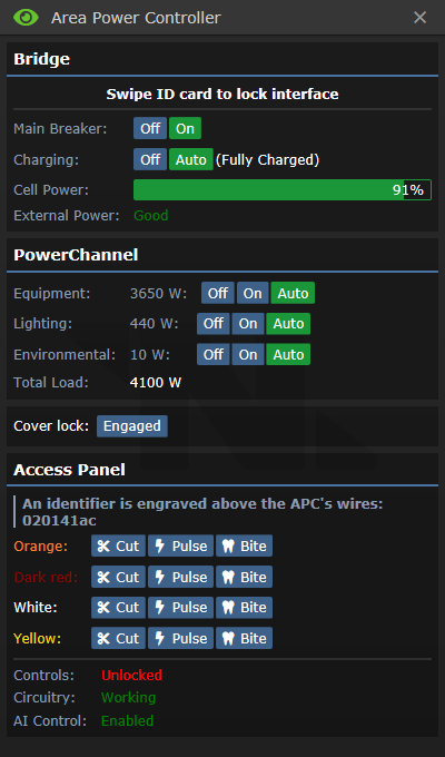
Clicking on an APC will open up its user interface. The APC controls can be unlocked by swiping an ID with "Electrical Systems" access, and silicons can modify the APC controls remotely if the AI control setting is not disabled. The APC access panel can be opened with a screwdriver, allowing you to see its NetID, interact with the wires, and check on the status of its systems.
From top to bottom, the UI elements are:
- Main Breaker: Controls whether the APC is attempting to power its area or not. Should usually be left to "on".
- Charging: Controls whether the APC is attempting to charge its internal power cell or not. Should usually be left to "auto".
- Cell Power: A readout of how charged the cell is. If power supply is in excess of demand, this will charge until 100%. Otherwise, the internal cell will contribute the difference between power demand and supply, until it is exhausted of power.
- External Power: Indicates if external power exists, and if it is enough to fully meet demand.
- Equipment: The main and usually highest-load power channel. Most things, such as doors, computers, fabricators, etc., run on the equipment power channel. In brownout conditions, when set to "auto" this power channel will automatically disable at 20% power remaining in order to conserve power.
- Lighting: Powers the normal lights for this area (but not the emergency lights). In brownout conditions, when set to "auto" this power channel will automatically disable at 35% power remaining in order to conserve power.
- Environmental: Powers fire alarms and firelocks, emergency lights, air scrubbers, and other high-priority equipment. In brownout conditions, when set to "auto" this power channel will not be automatically disabled, and will continue to provide power until the internal cell is entirely exhausted.
- Total Load: The total power draw of all powered equipment controlled by the APC, in watts.
- Cover Lock: Can be disengaged after unlocking the settings to allow the APC to be crowbarred open, to remove its power cell.
- Identifier: The APC's NetID, for communicating on the powered infra-network. This can also be read without opening the access panel by using a multitool on an APC.
- Colored Wires: These control the APCs functions. What function is controlled by which wire is randomized every shift, but all APCs within a shift use the same wires for the same function. One wire controls the controls lock, two wires control the main breaker, and one wire controls the remote control functionality for AI usage.
- Overload Lighting Circuit: The AI and Cyborgs have an option to overload the lighting circuit, causing all lights to pop in a shower of sparks. These sparks can burn people and ignite flammables such as fuel tanks, so silicons whos laws forbid them from human harm should not be doing this.
SMES
The SMES units are large capacitors that serve as a middle-point between the generators and the APCs on the power grid. They serve to turn the fluctuating raw power output from the generators into a consistent power power level for the rest of the power grid. They also can store energy, to serve as a buffer in the event that power generation fails. They are powered by an electrical terminal that is usually under the floor tiles adjacent to them, and output power to all wires that terminate under the SMES.
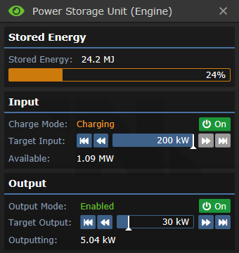
From top to bottom, the UI elements are:
- Stored Energy: The amount of energy in megajoules that are stored in the SMES. Storing and releasing energy occurs at 100% efficiency, so one megajoule is enough energy to output one megawatt for one second. A normal SMES can store up to 100 megajoules.
- Charge Mode: Shows whether the SMES input is charging, initializing (not enough power to charge), or offline. Pressing the On/Off button allows the user to toggle SMES charging.
- Target Input: The amount of power the SMES is set to intake. Maximum of 200 kilowatts. If power supply is greater than target input, the extra power may be used by other SMES units or the PTL, but is otherwise lost. If the power supply is less than the target input, the SMES will not charge at all.
- Available: The amount of power output by the generators that is not currently being used by other SMES units or the PTL. The order in which SMES units and the PTL take their share of power is dependent on the order they were loaded into the map, and is inconsistent between maps.
- Output Mode: Shows whether the SMES output is enabled (outputting the requested amount of power) or offline. Pressing the On/Off button allows the user to toggle SMES output.
- Target Output: The amount of power the SMES is set to output. Maximum of 200 kilowatts. If target output is greater than power demand, the extra power will be available to the grid but will not be consumed from the SMES. If target output is less than power demand, other SMES units will pick up the slack. If the sum of all SMES unit outputs is less than power demand, APC cells will begin discharging to make up the difference and power will eventually fail.
- Outputting: The amount of power the SMES unit is currently outputting in order to meet grid demand. The order in which SMES units contribute power to the grid is dependent on the order they were loaded into the map, and is inconsistent between maps.
Power Generators
The heart of any stable power grid, power generators are devices that convert some available resource into electric power. Every map has at least one built-in power source that is meant to power the station, which is to be set up by engineers. Maps set in outer space also have solar panels, which can help supplement or partially replace the primary generator output.
Solar Generator
Present on all maps set in outer space, solar panels produce power by collecting the radiant energy of the plasma giant, which for your purposes means for free. This makes them useful as a backup power source, if setting up the main generator may take longer than expected or if the main generator's output is unexpectedly low. However, their power output varies wildly depending on the angle between the station and the plasma giant, meaning that they cannot always be counted on to provide a certain amount of power.
The SMES units are rather inefficient at handling rapidly changing levels of low power output (as extra power is wasted, but having not enough power means the SMES doesn't charge at all). For this reason, it is common practice to hotwire the solars, meaning to directly wire them into the main power grid instead of routing the power through a SMES unit. The solars produce a relatively low amount of power, so it is not terribly dangerous for them to dump all of their power onto the grid. The APCs can then take as much power as they need, bypassing the SMES and resulting in greater efficiency.
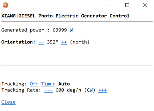
Each solar panel array will be wired to a solar panel control terminal, which contains stats and controls for the solar array.
From top to bottom, the UI elements are:
- Generated Power: The current output of the solar panels.
- Orientation: The current angle of the solar panels.
- Tracking: How the solar panel chooses the direction to point. "Off" means no automatic adjustments, "Timed" means that they adjust at a set rate, and "Auto" means that they use the connected solar tracker to automatically point towards the plasma giant. Unless the solar tracker is destroyed, this should usually be left on "auto."
- Tracking Rate: The set rate used by the "Timed" tracking setting.
Thermoelectric Generator
- Main article: Thermoelectric Generator
Present on Cogmap1, Cogmap2, Destiny, Clarion, Atlas, and Kondaru, the thermoelectric generator creates power from the temperature differential between very hot gas and very cold gas. It features two "loops" of gas piping: One with equipment designed to increase the gas temperature, and the other with equipment designed to decrease gas temperature. These two loops intersect inside the thermoelectric generator, where the heat flow from the hot loop to the cold loop creates electric power.
Singularity Generator
- Main article: Singularity Generator
Present on Donut 2 and Donut 3, the singularity generator creates power by harvesting the ionizing radiation emitted by a gravitational singularity. It features containment pylons and power emitters designed to hold the singularity in place and prevent it from consuming everything, and radiation collector arrays that use plasma to convert radiation into electric power.
Geothermal Generator
- Main article: Geothermal Generator
Present on Oshan Laboratory, the geothermal generator creates power by harvesting the thermal energy emitted by underground magma. It features stomper units that can lock a geothermal hotspot in place, and collector vents that can convert their heat into electric power.
Other Generators
Aside from the main generators that are designed to power the station, there are also other power sources that may be more suited to different purposes. Most of these are best used as auxiliary generators, as their output is usually more on the order of powering one room than an entire station.
Power Furnaces
Usually found on small off-station sites which have very low power draw, power furnaces can be loaded with flammable solids and produce five kilowatts of power when active. They can also be ordered by quartermasters in the basic power kit crate, alongside a SMES unit.
Experimental Local Generator
Orderable by quartermasters in the experimental local generator crate, these generators consume plasma from a small tank in order to charge the local APC or an inserted power cell. The amount of plasma consumed is directly proportional to the amount of power generated, and so leaving one on in a room with an APC that is not discharging its internal cell will not waste plasma.
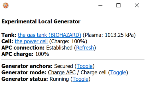
From top to bottom, the UI elements are:
- Tank: The inserted gas tank. Requires plasma inside to function.
- Cell: The inserted power cell. If not charging the local APC, the generator will charge this cell instead.
- APC connection: If the generator is connected to a local APC. After securing the generator, clicking "refresh" is required to it to find the APC and connect to it.
- APC charge: How charged the local APC's internal cell is.
- Generator Anchors: If the generator is secured in place. It will not function if not secured.
- Generator Mode: Whether the generator is attempting to charge the local APC or an inserted power cell.
- Generator Status: Whether the generator is on or not.
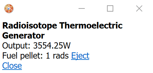
Radioisotope Thermoelectric Generator
Present on Clarion and Destiny, these generators use radioactive fuel pellets to produce power for the station grid. Their power output is extremely low, more fuel cannot be fabricated, and they use their fuel cells very quickly. For these reasons, radioisotope thermoelectric generators are almost never used.
From top to bottom, the UI elements are:
- Output: The generator's current power output.
- Fuel Pellet: The radioactivity of the currently inserted fuel pellet. Goes down over time as the pellet is consumed.
Artifact Generators
Occasionally discovered by artifact research, these artifacts can be connected to a wire to produce a random amount of power between five megawatts and five hundred megawatts. Clicking the artifact while it is over a wire will attach or detach it from the grid. Generator artifacts are extremely dangerous, and may cause shockwaves (breaking windows and stunning people) or electric arcs (causing burns or even outright disintegrating people) while active. If you wish to connect an artifact generator to the grid, it is advised that you get a clone scan before connecting it. In order for non-antagonists to prevent an artifact generator from being a danger to the station, a wire can be built from the generator grid into space, where the shockwaves and electric arcs are unlikely to hit anyone. Pay special care to not wire the generator into the APC grid, as this will cause APCs to emit electric arcs from overvoltage.
Power Transmission Laser
The power transmission laser can be used to convert excess power into cash. It operates like a SMES unit, with two major differences: It can store a much greater amount of power (one petajoule, or 10^15 joules), but it cannot output to the power grid. Instead, it fires a high-energy laser out into space, presumably at someone willing to pay to have a high-energy laser fired at them. The revenue generated by the PTL is governed by the following formula:
What the PTL does to mobs that touch the beam is also dependent on how powerful it is. Below one hundred megawatts it only sets mobs on fire. Between one hundred megawatts and five gigawatts, it does direct damage, and has a chance to slice off a limb. Above five gigawatts, it instantly gibs any mob that touches the beam. Above one terawatt, this death will be so violently explosive that it can actually breach the station hull. For aspiring crimers, do note that anyone who is gibbed by the PTL for the first time get the For Your Ohm Good medal, which is announced to the whole server and may foil your stealthy corpse disposal plans.
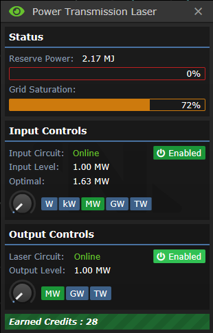
Most of the elements of the UI look and function identically to the SMES unit's UI. The elements unique to the PTL are:
- Grid Saturation: The ratio of the amount of power being used to the amount of power produced. This value being closer to 100% means that the PTL is closer to the optimal setting.
- Optimal (input): The amount of power available for the PTL to use. In theory, setting the PTL to exactly this number is the most efficient setup. In practice, in order to avoid PTL outages due to slight power fluctuations and to allow the SMES units to have the power they need, setting it at least one megawatt lower than the optimal setting is advised.
- Earned credits: The amount of cash the PTL has earned during the whole shift. The money earned by the PTL is automatically routed towards the relevant budgets: One half is given to the station payroll (which the HoP can distribute as they see fit), and the other half is payed directly into the engineers' bank accounts. Each engineer gets an even share of the loot, except the chief engineer who gets two shares.


