Powering the station
There are two distinct ways to supply the station with electricity, which can either be used exclusively or in combination with each other. The solar arrays are efficient and simple, yet leave no room for experimentation. In contrast, there are probably as many different engine setups as there are engineers.
The solar arrays

Solar arrays are not a complicated affair and provide a decent amount of power once properly configured. This task can be handled by the AI in the first few minutes of any given round, which is great when the engineers have no clue how to do their job. They're also a single wire snip away from sabotage, so they should not be relied on completely in lieu of the generator if possible.
How it all works
Each array is a fully automatic and for the most part self-contained system. It consists of:
- The solar tracker, which tracks the location of the sun.
- Solar panels to generate electricity.
- The control terminal, which aligns the panels to the sun.
- The array's output is channeled through a SMES unit, basically a huge rechargeable battery. For the connection, an electric terminal (not to be confused with data terminals) is required.
- Regular wiring then feeds a certain amount of power (depending on the SMES settings) to the station grid.
Auto-tracking doesn't work when there is no continuous connection between the tracker and control terminal. Damaged wiring will also prevent panels from rotating automatically, as they can't receive commands from the computer.
Note: The computer is tied to the APC's equipment setting. If the APC has been switched off or drained at any point, it is necessary to reset the tracking program from Auto to Off and back to Auto.
Method #1: Configure the SMES units
Making use of SMES units is feasible for the duration of a typical shift, but it won't leave much reserves if telescience decides to play around with permaportals or something unforeseen happens.
- 1. Chose an appropriate Input value from the table below for the solar array in question.
- 2. Make sure the Input is set to Auto, though it should be already.
- 3. Likewise, pick the corresponding Output value.
- 4. Set the Output to Online.
| Array | Image | Peak output | Suggested input |
Suggested output |
Info |
|---|---|---|---|---|---|
| Aft (bridge maint.) |
 |
~90.000 W | 53.000 | 25.000 | The smallest and thus least powerful array. It generates around 54000 W on average, so overoptimistic settings will deplete the SMES unit quickly. |
| Port (catering maint.) |
 |
~120.000 W | 75.000 | 40.000 | Don't set the output too high. Due to the way the power grid code works, it is second in line after the aft solars and will always be loaded. |
| Starboard (near tech storage) |
~120.000 W | 85.000 | 60.000 | Pretty much identical to the port solars. Because it is last in line after the four engine substations (which amount to 40.000 W combined output by default), there is more leeway to use it as a buffer. |
Keep in mind that the sun will always be moving in relation to the station, which means that the amount of electricity generated by each array won't be constant. For this reason, it's also best to leave the control terminal on the default settings (i.e. Auto) unless you want to babysit the arrays and rotate them manually.
In case you consider deviating from these suggestions, be aware of two other things. The SMES unit's input should be set with a value no higher than what is indicated on the control terminal. It won't charge if it is set higher than what the arrays are producing, even if the difference is only a couple of watts. In addition, the output should have a value lower than the input in order to build up some reserves, because the SMES won't always be charging.
Method #2: Hotwiring

This is the preferred option if you have access to basic tools, a pair of insulated gloves and the three substations.
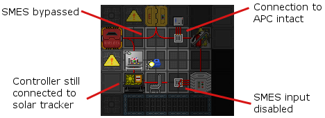
- 1. Bypass the SMES by bridging the obvious gap on the floor. For more information on how to lay wires, please refer to Guide to Wiring.
- 2. Disable the SMES on the input side. Setting its input to Off has the same effect, but this way ensures that the AI can't interfere. The solar arrays don't generate enough electricity to supply the station and charge the SMES units at the same time.
- 3. Double-check that you didn't disconnect the control terminal or APC by accident.
As mentioned before, solar arrays don't produce a constant amount of power. While eliminating the SMES units from the equation does deprive the system of a buffer, there is almost always enough juice available to keep the APCs supplied, even if a single array may contribute only 25.000 W to the total number. Typically, the station demands circa 130.000 W.
The thermoelectric generator
File:UpdatedEngineSchematic.png
How it all works
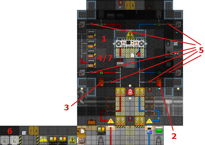
The engine has three segments:
- The hot loop, where heat is generated by heating gas in the furnaces, the combustion chamber or using a mixture that creates fire right in the pipes.
- The cold loop that absorbs heat and radiates to space.
- The generator which transfers heat from the hot to the cold loop and produces power.
Four passive gates around the loop keep the gas flowing.
Each primary canister hookup has its own pump, to increase or decrease the speed of gas injection of into a loop.
The vents at both sides of engineering allow you to remove excessive pressure or scrub a loop of unwanted gas.
Gas
Gas has some important properties, pressure temperature and heat capacity.
- Pressure directs the gas flow from higher to lower pressure pipe segments. If pressure it too high in a pipe, pumps will not be able to move gas, and power output will drop.
Above 17,000 kPa, pipes have a chance to burst! Check the meters, and use your PDA or an analyzer on a pipe to read its pressure.
- Temperature causes gas to increase or decrease in pressure. Very little gas when heated can reach gigantic pressure. Conversely, gas in the cold loop will most often be at a low pressure.
- Heat capacity is different for each gas, it determines how quickly a gas can absorb and transfer heat.
Any gas can be used as a medium in both pipe loops; and each gas has a different ability to retain heat or transfer it more quickly. Generally, safer gases will yield much lower power outputs.
Experimenting with different gas in each loop will let you discover which combinations work best, and how to control the most dangerous gas mixtures.
Pressure
The engine can be efficiently run on very small quantities of gas. Filling the pipes with entire canisters of gas will increase the chance of pressure issues. Injecting small quantities of gas in the loops and the combustion chamber over time reduces waste and allows for very high power outputs.
Too high pressure inside a pipe will cause it to fracture and leak gas. A broken pipe can be repaired by welding.
Pressure imbalances that stop the correct flow of gas can be controlled by venting gas (either to a canister, or to space). Venting is more effective when gas flow is temporarily blocked by shutting down the proper valve.
An example to get you started

The following setup is safe, straight-forward and almost maintenance-free. If it is your first day on the job, it may be useful as a starting point, to observe how the engine behaves under load. Or perhaps you're just interested in something nice and easy to keep the lights on.
- 1. Dump some char ore in the furnaces.
- You can find char ore in the metal boxes in the storage room northeast of the engine chamber.
- 2. Connect one tank of plasma to the cold loop auxiliary port.
- You can find plasma canisters in the same storage room. You need to pull the tank atop the port, then lock it into place with a wrench.
- 3. For the hot loop, take a canister of plasma and connect it to the auxiliary port on the opposite side.
- 4. Activate the furnaces.
- It is imperative that you do this before the next step. Doing it the other way around may trigger a glitch and render the setup useless.
- 5. Open the corresponding valves.
- 6. Set both SMES units to 200.000 input and 100.000 output.
- 7. Come back ~30 min later and load more ore in the furnaces.
If you follow these steps correctly, the engine should generate a steady ~1.3 MW for the duration of a typical shift. Plasmastone, when available, can be used to increase the output.