Difference between revisions of "Thermoelectric Generator"
(Added more detail to TEG core, finished semiconductor, finished furnaces.) |
(finished hot loop and burn chamber text) |
||
| Line 78: | Line 78: | ||
</tabs> | </tabs> | ||
The hot loop is all of the pipeworks and equipment dedicated to heating gas and pushing it through the TEG. It features two gas tank ports designed to inject plasma or another gas into the hot loop pipes for the purpose of conducting thermal energy. In order to raise the temperature of the gas, the hot loop comes equipped with furnaces and a burn chamber. The hot loop pipes are a distinct red color, as are the floor tiles in most hot loop rooms. | |||
====Furnaces==== | ====Furnaces==== | ||
| Line 85: | Line 88: | ||
====Burn Chamber==== | ====Burn Chamber==== | ||
The burn chamber is the other method of generating heat in the hot loop. Using the combustion of plasma and oxygen over a hot loop radiator, it can create significantly higher temperatures than the furnaces are capable of. Like the hot loop pipes, the burn chamber has two gas tank ports designed to add gas to the chamber. Unlike the pipes however; these connector ports feed into a special gas mixer pump before reaching the burn chamber. Using the associated mixer pump control terminal, you can set the ratio of the contents of the two gas tanks and the pressure at which they are released into the burn chamber. While experimental burns may benefit from more precise mixer settings, leaving the pump set to a 1:1 ratio of oxygen and plasma at atmospheric pressure (101.325kPa) will ensure a long-lasting and hot burn. | |||
Do note that the burn chamber is not perfectly insulated. A particularly hot burn will heat up the chamber walls, causing heat to conduct out of the chamber and into the surrounding areas. While the heat shields button to deploy shields over the observation windows may help somewhat, it is common practice to use an RCD to cut holes in the floor of the surrounding rooms, venting the engine room and preventing it from spreading dangerously hot gas to the rest of the station. | |||
===Cold Loop=== | ===Cold Loop=== | ||
Revision as of 18:56, 24 October 2022
| This page is under construction. The following information may be incomplete. Pending construction as part of a phasing out of Powering_the_station (yes, its capitalization was inconsistent) for a less wrong engineering guide. |
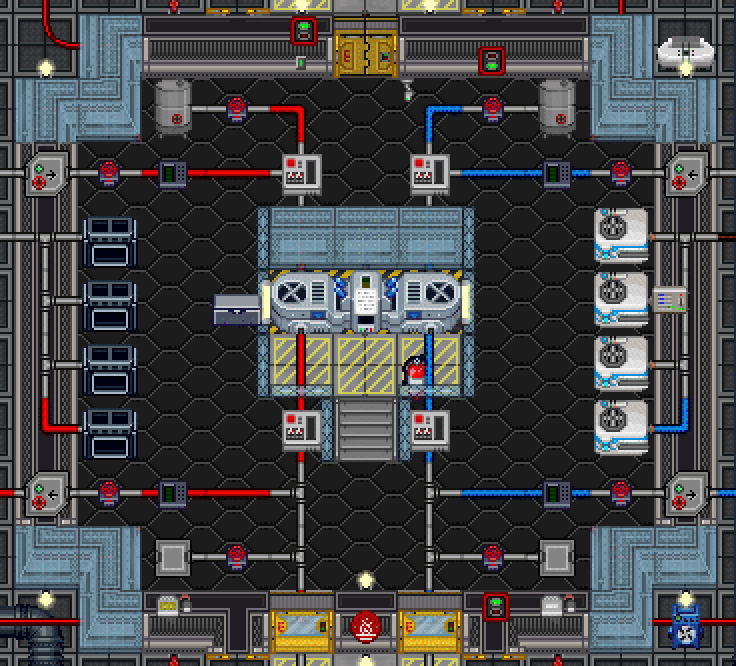
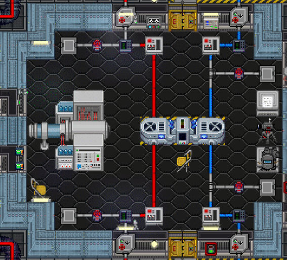
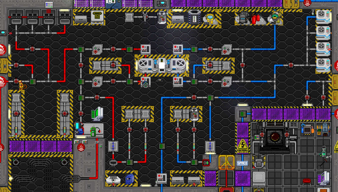
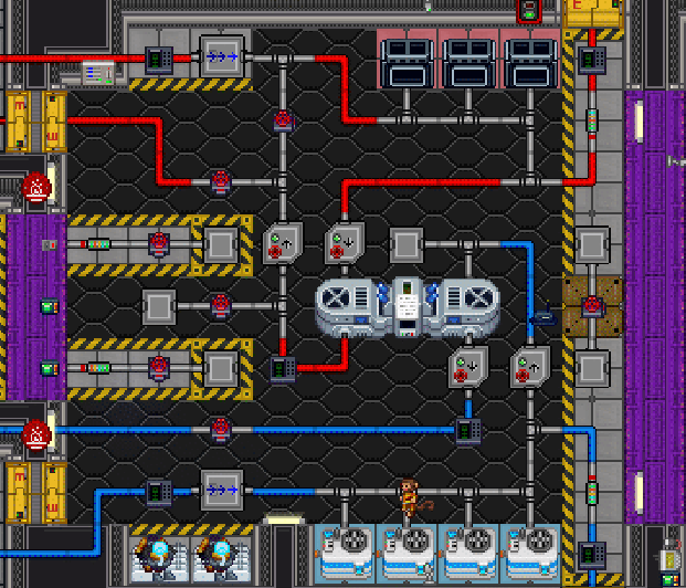
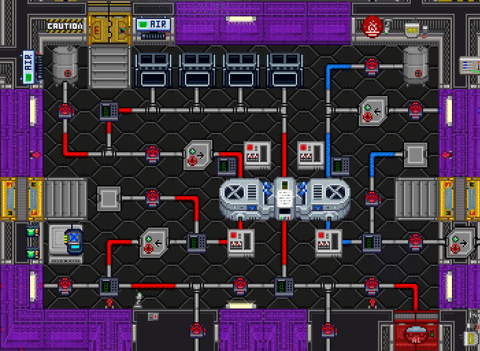
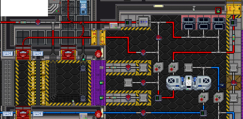
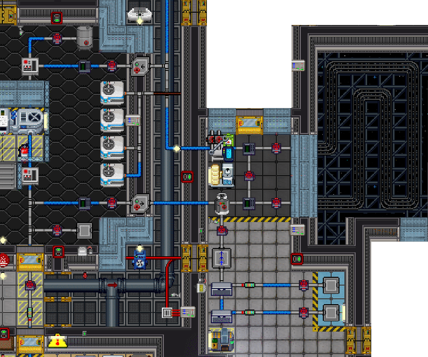
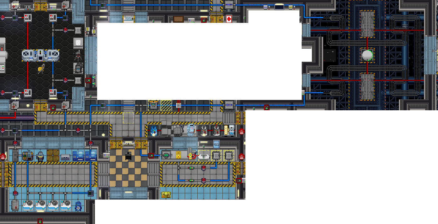
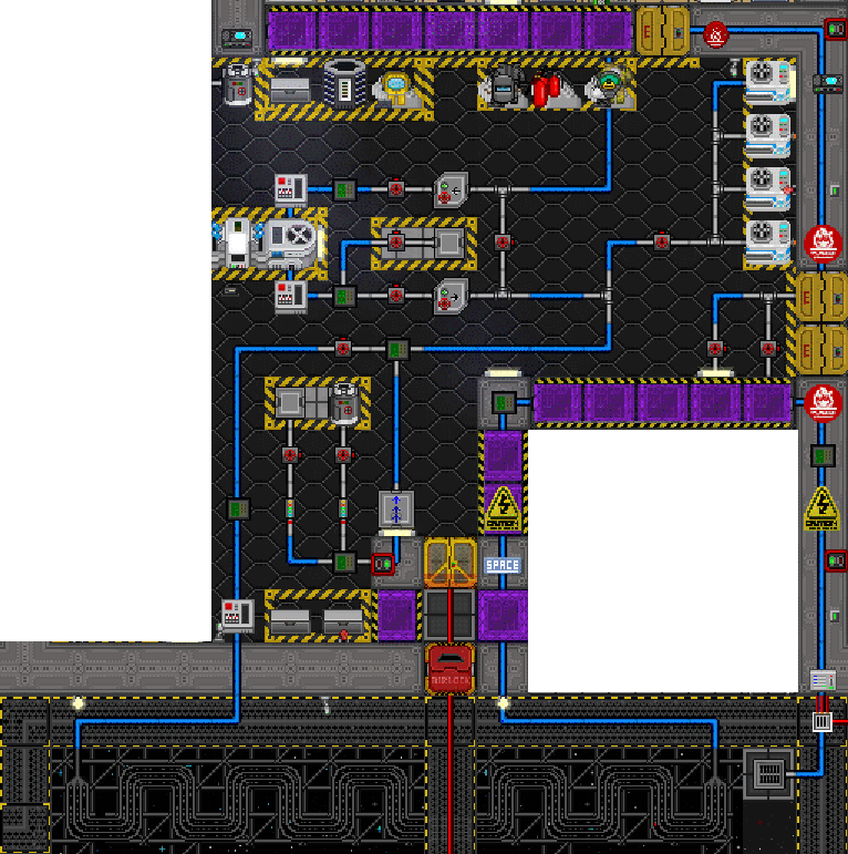
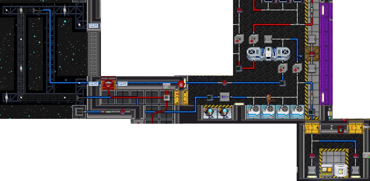
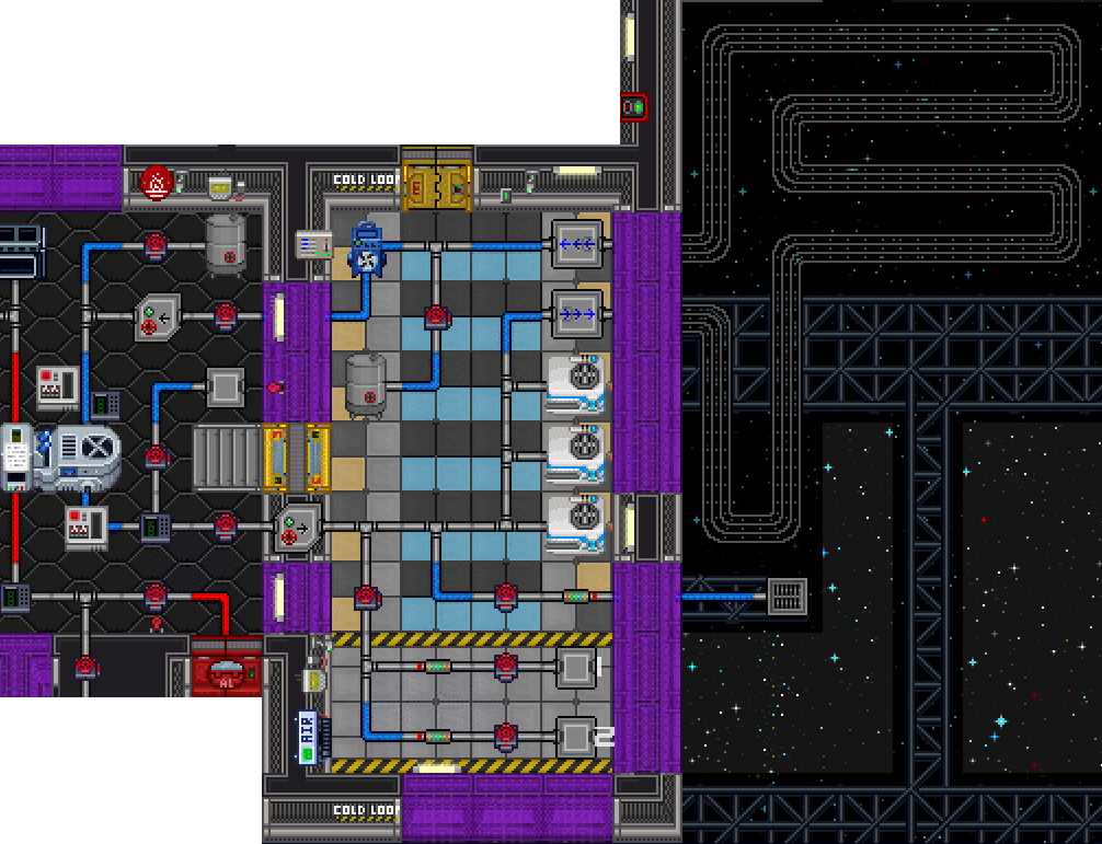
The thermoelectric generator (TEG) is the main source of power on Cogmap1, Cogmap2, Clarion, Atlas, and Kondaru. It generates power via the thermal interaction of hot gas and cold gas inside the generator. In order to create and maintain a supply of hot and cold gas, two separate loops of gas pipes move through the TEG: The hot loop and the cold loop. As their names imply, the hot loop has equipment designed to heat up the gas within, and the cold loop has equipment designed to cool down the gas within.
Parts of the TEG
Core
The TEG core itself is what makes the electricity. It functions by taking a part of the heat energy conducted between the hot loop and cold loop and converting it into electrical power. The central part of the TEG contains a status terminal, which can give you stats on the current power output, the pressure of the inlet and outlet of both gas loops, and the temperature of both gas loops. The graphic displayed on this terminal represents the current power generation of the TEG. Even the graphics that seem to indicate danger, like skulls and explosions, are only indicative of power output and are not a cause for concern.
The TEG core also features some warning lights next to the blowers. These lights will be blue when blower status is nominal. If the blowers are consuming more power than the APC is receiving, the lights will turn yellow when power is expected to fail within the next five minutes, and will turn red when power is expected to fail in one minute. Due to the questionable math involved in power calculations, the lights turning yellow should not be cause for any concern unless it does not turn blue again after a minute or so.
Blowers
The turbines on the left and right sides of the TEG are gas blowers designed to help increase the flow of gas through the TEG. Using a multitool, their target minimum pressure can be set, and they can be turned on and off. While on, the blower will attempt to pull gas through the pipe in order to maintain at least as much outlet pressure as the specified value. They consume power from the local APC while active, with the power draw being determined by the the difference between the outlet pressure and the inlet pressure. Larger pressure differentials require more power to push gas against.
Lubricant
The maintenance panel on the blowers can be accessed by using a screwdriver on them. Each blower contains a lubricant tank, which starts filled with 200 units of oil. The lubricant tanks can be emptied by using a wrench on them to open the drain caps, which will leak the existing lubricant onto the floor. Remember to close the drain caps before adding new lubricant in order to not waste it.
The quality of the lubricant effects how effectively and power-efficiently the blowers are able to operate against a pressure differential, with more slippery chemicals such as space lube and organic superlubricant providing greater efficiency. The total blower boost from the lubricant is based on the quantity and quality of the lube, meaning that filling the blowers to capacity will be more effective.
Other chemicals may do even more things aside from just lubricating the blowers. For example, pyrosium or cryostylane reacting with oxygen in the blowers will change the temperature of the gas that passes through the blower.
Semiconductor
Inside the central piece of the TEG is a prototype semiconductor, which can be removed by using a screwdriver, then wirecutters, then a crowbar on the TEG. After being removed, the semiconductor can be plated in another material using the arc electroplater, which will change how efficiently the TEG extracts electrical power from the heat exchange. For optimal engine performance, a semiconductor that is electrically conductive and thermally insulative is ideal. To re-add the semiconductor to the engine, use the semiconductor, then wires, then wire cutters, then a screwdriver.
Hot Loop
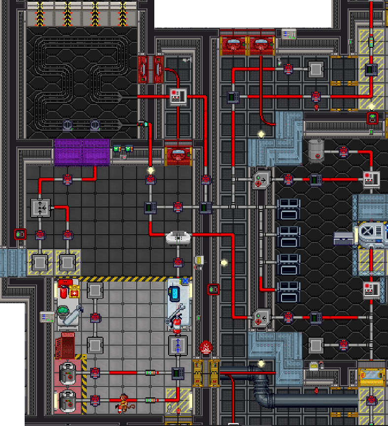
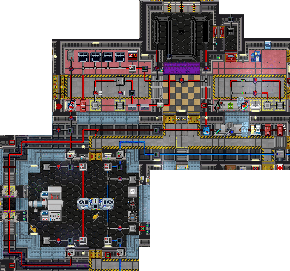
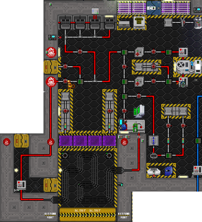
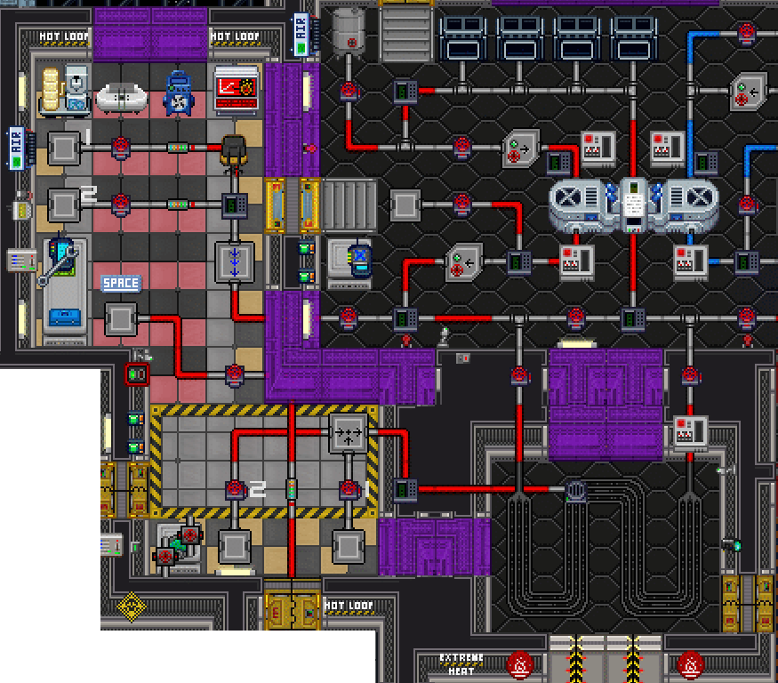
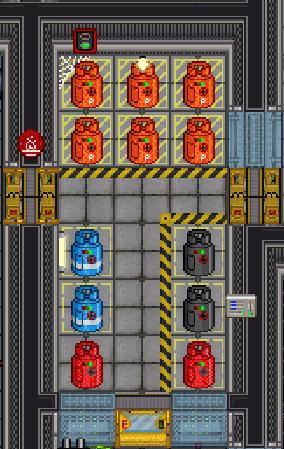
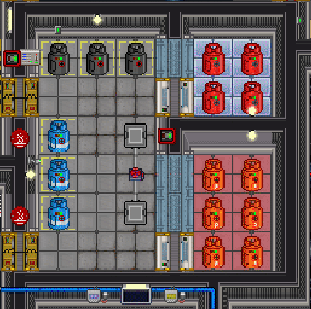
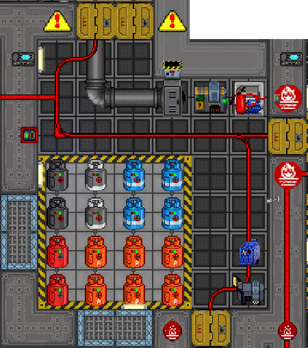
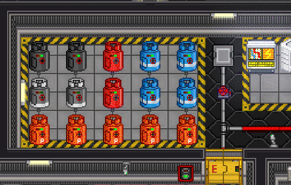
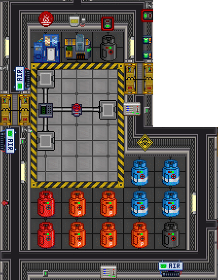
The hot loop is all of the pipeworks and equipment dedicated to heating gas and pushing it through the TEG. It features two gas tank ports designed to inject plasma or another gas into the hot loop pipes for the purpose of conducting thermal energy. In order to raise the temperature of the gas, the hot loop comes equipped with furnaces and a burn chamber. The hot loop pipes are a distinct red color, as are the floor tiles in most hot loop rooms.
Furnaces
The furnaces can accept any flammable solid as fuel. The most readily available is char, but plasmastone, weed, paper, and even corpses can be used as fuel. Different types of fuel do not burn hotter, though more flammable things will fill up the furnace more than less flammable things. The furnace heats to roughly 3200 kelvin when full, and starts to notably drop off in temperature when less than 2/3 full.
Do note that the furnaces attempt to force the gas in the loops towards their output temperature, regardless of whether this means heating the gas or cooling it. If you have a decently hot chamber burn running, running the furnaces will actually cool your hot loop down.
Burn Chamber
The burn chamber is the other method of generating heat in the hot loop. Using the combustion of plasma and oxygen over a hot loop radiator, it can create significantly higher temperatures than the furnaces are capable of. Like the hot loop pipes, the burn chamber has two gas tank ports designed to add gas to the chamber. Unlike the pipes however; these connector ports feed into a special gas mixer pump before reaching the burn chamber. Using the associated mixer pump control terminal, you can set the ratio of the contents of the two gas tanks and the pressure at which they are released into the burn chamber. While experimental burns may benefit from more precise mixer settings, leaving the pump set to a 1:1 ratio of oxygen and plasma at atmospheric pressure (101.325kPa) will ensure a long-lasting and hot burn.
Do note that the burn chamber is not perfectly insulated. A particularly hot burn will heat up the chamber walls, causing heat to conduct out of the chamber and into the surrounding areas. While the heat shields button to deploy shields over the observation windows may help somewhat, it is common practice to use an RCD to cut holes in the floor of the surrounding rooms, venting the engine room and preventing it from spreading dangerously hot gas to the rest of the station.

