User:Cherman0/Power Grid
From lights to doors to fabricators to computers, just about everything on the station needs electricity to run. The power grid is the entire system of infrastructure that generates, stores, and directs electrical power to the devices that need it to operate. This page serves as an overview of all of the essential infrastructure of the power grid. More specific details on the operation of specific engine types may be found in their own respective pages.
Wires
Power wires are routed through maintenance tunnels and under floor tiles in order to connect the generators to SMES units, and the SMES units to APCs. Breaks in the wire grid may cause certain equipment to not receive power, causing partial blackouts. A few select objects (such as meteor shields) may also be wrenched onto a wire in order to draw power directly from the wire, bypassing the APC or internal battery cell.
APC
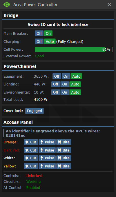
Short for Area Power Controller, APCs are small grey electrical panels that handle the power draw of one room. They are powered by a wired connection to an electrical terminal in the floor under the APC, and they power other devices wirelessly through "safe" wireless power transmission. APCs have an internal power cell, which allows them to provide stable power even in intermittent power conditions, and provides a few minutes of buffer time should power fail entirely. Clicking on an APC will open up its user interface. The APC controls can be unlocked by swiping an ID with "Electrical Systems" access, and silicons can modify the APC controls remotely if the AI control setting is not disabled. The APC access panel can be opened with a screwdriver, allowing you to see its NetID, interact with the wires, and check on the status of its systems.
From top to bottom, the UI elements are:
- Main Breaker: Controls whether the APC is attempting to power its area or not. Should usually be left to "on".
- Charging: Controls whether the APC is attempting to charge its internal power cell or not. Should usually be left to "auto".
- Cell Power: A readout of how charged the cell is. If power supply is in excess of demand, this will charge until 100%. Otherwise, the internal cell will contribute the difference between power demand and supply, until it is exhausted of power.
- External Power: Indicates if external power exists, and if it is enough to fully meet demand.
- Equipment: The main and usually highest-load power channel. Most things, such as doors, computers, fabricators, etc., run on the equipment power channel. In brownout conditions, when set to "auto" this power channel will automatically disable at 20% power remaining in order to conserve power.
- Lighting: Powers the normal lights for this area (but not the emergency lights). In brownout conditions, when set to "auto" this power channel will automatically disable at 35% power remaining in order to conserve power.
- Environmental: Powers fire alarms and firelocks, emergency lights, air scrubbers, and other high-priority equipment. In brownout conditions, when set to "auto" this power channel will not be automatically disabled, and will continue to provide power until the internal cell is entirely exhausted.
- Total Load: The total power draw of all powered equipment controlled by the APC, in watts.
- Cover Lock: Can be disengaged after unlocking the settings to allow the APC to be crowbarred open, to remove its power cell.
- Identifier: The APC's NetID, for communicating on the powered infra-network. This can also be read without opening the access panel by using a multitool on an APC.
- Colored Wires: These control the APCs functions. What function is controlled by which wire is randomized every shift, but all APCs within a shift use the same wires for the same function. One wire controls the controls lock, two wires control the main breaker, and one wire controls the remote control functionality for AI usage.
- Overload Lighting Circuit: The AI and Cyborgs have an option to overload the lighting circuit, causing all lights to pop in a shower of sparks. These sparks can burn people and ignite flammables such as fuel tanks, so silicons whos laws forbid them from human harm should not be doing this.
SMES
The SMES units are large capacitors that serve as a middle-point between the generators and the APCs on the power grid. They serve to turn the fluctuating raw power output from the generators into a consistent power power level for the rest of the power grid. They also can store energy, to serve as a buffer in the event that power generation fails. They are powered by an electrical terminal that is usually under the floor tiles adjacent to them, and output power to all wires that terminate under the SMES.
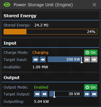
From top to bottom, the UI elements are:
- Stored Energy: The amount of energy in megajoules that are stored in the SMES. Storing and releasing energy occurs at 100% efficiency, so one megajoule is enough energy to output one megawatt for one second. A normal SMES can store up to 100 megajoules.
- Charge Mode: Shows whether the SMES input is charging, initializing (not enough power to charge), or offline. Pressing the On/Off button allows the user to toggle SMES charging.
- Target Input: The amount of power the SMES is set to intake. Maximum of 200 kilowatts. If power supply is greater than target input, the extra power may be used by other SMES units or the PTL, but is otherwise lost. If the power supply is less than the target input, the SMES will not charge at all.
- Available: The amount of power output by the generators that is not currently being used by other SMES units or the PTL. The order in which SMES units and the PTL take their share of power is dependent on the order they were loaded into the map, and is inconsistent between maps.
- Output Mode: Shows whether the SMES output is enabled (outputting the requested amount of power) or offline. Pressing the On/Off button allows the user to toggle SMES output.
- Target Output: The amount of power the SMES is set to output. Maximum of 200 kilowatts. If target output is greater than power demand, the extra power will be available to the grid but will not be consumed from the SMES. If target output is less than power demand, other SMES units will pick up the slack. If the sum of all SMES unit outputs is less than power demand, APC cells will begin discharging to make up the difference and power will eventually fail.
- Outputting: The amount of power the SMES unit is currently outputting in order to meet grid demand. The order in which SMES units contribute power to the grid is dependent on the order they were loaded into the map, and is inconsistent between maps.
Power Generators
Solars
Thermoelectric Generator
Singularity
Geothermal
Other Generators
Power Furnaces
Experimental Local Generator
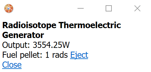
Radioisotope Thermoelectric Generator
Artifact Generators
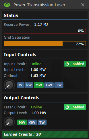
Power Transmission Laser
